
Workflow

From geometry to a decision, step by step.

The flow of data through the Workbench: the main analysis path, results into the calculators, thermal and thermal stress, fluid flow into the structure, and dynamic analyses.

The main path

One workflow for every analysis

Geometry in, results out. Optional steps such as contacts and refinement plug into the same line.

GeometryBuild featuresor import STEP, IGES, BREPSolid checkFind and repairfaults in imported CADMeshHex, tetra, curved-fitlinear or quadraticSupports and loadsFixed, sliding, force,pressure, gravity, thermalSolveFortran solveron the serverResults and reportContours, tables, probesPDF reportContactsbetween separate bodiesRefinementfiner mesh near facesand wall layersSend to toolsresults fill calculatorinputsRe-runchange and solve again
Every analysis follows the same path. Dashed boxes are optional steps that feed the main line.
Calculator plus FEM

167 tools check themselves.

Enter the part once. The tool does the hand calculation, builds a full three-dimensional finite element model of the same part, solves it, and puts the two side by side with a written comment. No symmetry cuts: the whole part is modelled. The check covers plates and shells, beams, shafts and torsion, trusses and axial members, lugs, bolted and bonded joints, fittings, and thermal and vibration problems. Where a finite element model would mean nothing, as in lookups, unit conversions and buckling-only screens, the tool says so instead of showing a made-up check. A sensitivity study runs automatically as well, varying each input in turn to show which ones drive the result.

1 · INPUTS

Describe the part

Size, thickness, material, edges and pressure. Example: a 12 by 8 in plate, 0.25 in 7075-T651, clamped edges, 10 psi.

2 · HAND CALCULATION

Timoshenko and Roark

The classical plate result for the same case: centre deflection and largest bending stress, with margins of safety.

3 · AUTOMATIC FEM

Full 3D model

The server meshes the whole plate with quadratic brick elements, applies the pressure and the clamped edges, and solves it.

4 · COMPARE

Results and comment

Deflection, stress and strain from both methods, the ratio, and a plain-language comment on any difference.
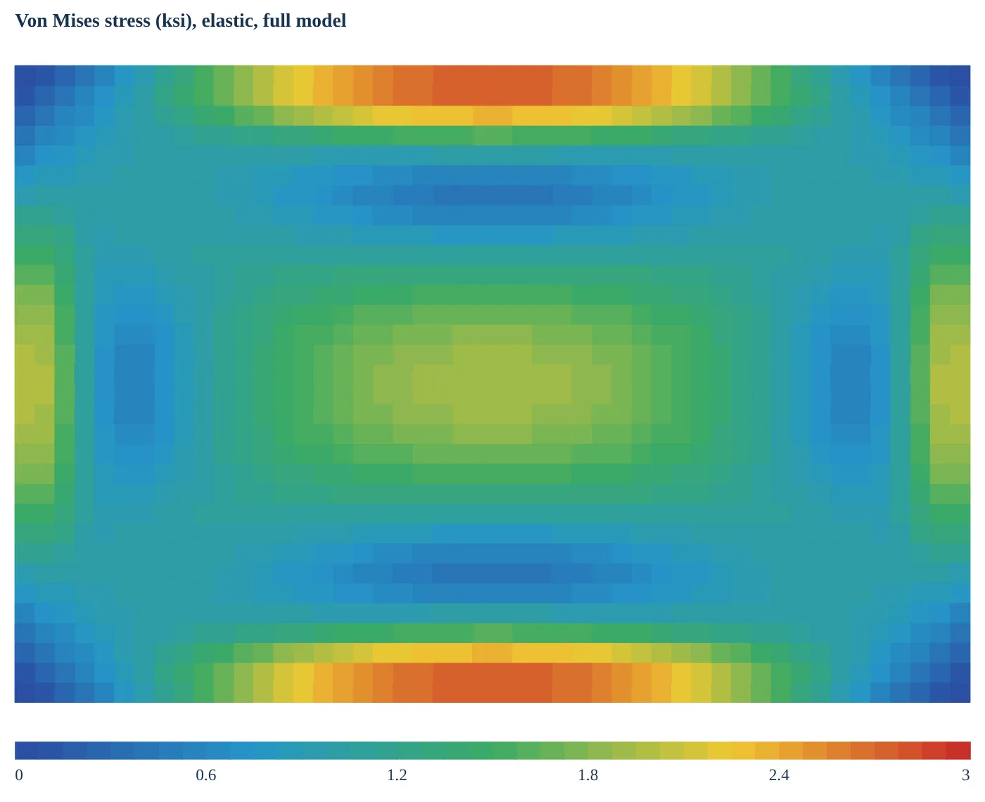
Von Mises stress contour on the full finite element model of a clamped rectangular plate under pressure
The FEM result picture the tool returns: the whole clamped plate, 768 quadratic brick elements.
ResultHandFEMFEM / hand
Centre deflection0.00599 in0.00593 in0.991
Largest bending stress4,651 psi4,637 psi0.997

Comment returned: the hand calculation and the FEM agree, so the thin plate formulas describe this part well. Where they do not agree (a thick plate, a large deflection) the comment says why.

One button downloads the same model as a Workbench file, so the check can be refined with your own mesh, loads and contacts. Available on every tool that carries the check.

Results to tools

FEM output straight into the calculators

Take a force, moment, stress or temperature from the model and drop it into the matching hand-calculation tool.

Workbench resultsForces and reactionsMomentsStresses and strainsPressuresTemperaturesDeflectionsSend results to a toolPick a tool and the valuesto sendLoads and marginsBeams and framesJoints and fastenersPressure and shellsbuckling, thermal, moreTool openswith inputs filledSI units banneryou check and run
Results go straight into the engineering calculators, so a detailed model and a hand check use the same numbers.
Thermal

Heat, time and thermal stress

Steady and transient heat flow share one thermal model. Thermal stress runs the temperatures into a structural solution.

Thermal modelFixed temperature, filmcoefficient, heat generationTime historyInitial temperature,heating or cooling stepsSteady thermalTemperatures atequilibriumTransient thermalTemperatures at eachtime stepTemperatureson every nodeStatic stresswith thosetemperaturesThermal stressexpansion, restraint,gradients
Thermal stress is one analysis type: the temperatures are solved first, then the stresses they cause.
Fluid flow

CFD into the wall and the structure

Solve the gas path, then pass its heating to the pipe wall for a thermal and stress answer.

Fluid solidinside of the duct,meshed with tetrahedraInlet and outletfaces marked,others are wallsFlow solvepressure drop, Reynoldsnumber, wall y+, MachGas heat transfergas temperature,heat into the wallsWall facesfilm coefficient andgas temperature mapped(one way)Outside aircoefficient andair temperatureWall thermaltemperatures solvedthrough the wallThermal stressstress from walltemperatures andrestraintoptional loop: re-run the flow with the wall temperature
The flow run solves the gas path; its film coefficient and gas temperature then load the pipe wall for a thermal stress run.
Dynamics

Transient, harmonic, random and shock

Start from the natural frequencies, then pick the loading that matches the environment.

Modelmesh, material,supportsNatural frequenciesmode shapesand frequenciesTransient structuralstep, ramp, pulse, sineor table load historyHarmonic responseswept sine, responsecurve, peak cycleRandom vibrationacceleration PSD: g RMS,1-sigma and 3-sigmaResponse spectrumshock spectrum, modalcombination SRSS or CQCResultstime histories, responsecurves, mode shapes
Natural frequencies and mode shapes guide the harmonic, random vibration and shock analyses; the transient solution steps the model through a load history directly.

See the flows on your own model.

Contact us to get access and run one of the worked examples in a few minutes.